The information contained on this page applies to Tiger Panel Meters, Bargraphs and Process Controllers / Micro PLC products.
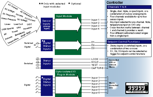
The Tiger 320 Series controller can be configured with up to four analog input signals and, depending on the options selected, 13 digital inputs.
The analog input signals can be either configured to display up to four different calibrated scaled ranges from a single input, or up to four individual inputs displayed independently on the four channels.
The Tiger controller can produce a result from maths performed between two inputs via channel 1 and channel 2, selected from a dual, triple, or quad input module.

Sensor Inputs
Depending on the input module selected, any of the available sensor inputs can be selected for processing through any of the four channels. Temperature inputs are always processed through channel 1.
The input module range for the Tiger controller consists of single, dual, triple, quad and smart input modules. Smart input modules have on-board digital signal processors that offload processing functions from the Tiger controller, leaving it free to perform advanced automation functions.
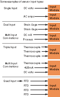
While some of the input modules are single sensor input types, a number of them are multi-sensor input combinations such as thermocouple and DC volts; thermocouple, DC volts, and DC millivolts; or thermocouple and dual 4-20 mA.
Opposite are some examples of sensor input types for single, dual, triple, and quad input modules. Go to Input Module page for a complete list.

Multi-Scaled Display Options
Using a single scaled and calibrated input signal displayed on channel 1, the same input signal can be displayed over other scaled ranges on channels 2, 3, and 4.

Digital Status Inputs
When connected to the COMMON pin, status input pins LOCK, HOLD, TEST, and CAPTURE on the Tiger controller can be used for a number of digital input functions. The LOCK, HOLD, and TEST pins are configured in Code 9 of the controller's main programming mode when programming through the front panel controls. The CAPTURE pin is configured via setpoint control in the setpoint programming mode for setpoint control and register reset functions. The functions of all four status input pins can be controlled by a macro.
Further digital status inputs are available on selected input modules. Depending on the input module selected, digital status inputs D1, D2, and D3 can be either switched or digital inputs, or a combination these. They are also configured via setpoint control or controlled by a macro. An optional opto-isolated I/O plug-in module supports a further six digital inputs for use exclusively with a macro.
Following is a list of selectable digital input functions for the TEST, LOCK, and HOLD pins when programming through the front panel controls. Bold type in the list indicates the default selection when connected to the COMMON pin. These settings can be changed by entering Code 9, or by using the configuration utility program via the serial port.
CODE 9 - FUNCTIONS FOR DIGITAL INPUT PINS
DISPLAY TEST PIN
- 0 Display test only
- 1 Reset Counter Channel 1 and total 2 at Power-up
- 2 Reset Counters Channel 1, 2, 3, 4, Total 1, and Total 2 at Power-up
- 3 Reset Total 1, and Total 2 at Power -up
HOLD PIN
- 0 Display Hold
- 1 Reset Channel 1
- 2 Reset Total 1 and Total 2
- 3 Reset Total 2
- 4 Reset Peak, Valley
- 5 Clear Tare
- 6 Set Tare
- 7 Unlatch (de-energize) all Setpoints
LOCK PIN
- 0 Key Lock
- 1 Reset Channel 1
- 2 Reset Channel 2
- 3 Reset Channel 3
- 4 Reset Channel 4
- 5 Clear Tare
- 6 Reset Total 1
- 7 Unlatch (de-energize) all Setpoints